Showing posts with label construction. Show all posts

Friday, 21 June 2019

Bi Polar Junction Transistor (BJT): Introduction, Construction and Working


Introduction:

BJT stands for Bipolar Junction transistor which means two polar junctions. The reason it is called Bipolar is that it uses both electrons and holes for carrying charge or to flow the current. While FET is known as a unipolar transistor.

Construction:

As we have discussed diode before, and how it is formed by the junction of two regions, P doped region, and n doped region. The BJT is formed by the combination of two back to back diodes. The Bipolar junction transistor or BJT has two junctions of the semiconductor. In one of the two types (PNP), a thin n-region is shared by two p-regions. And in another type (NPN), a thin p-region is shared by two n-regions, the figure below explains this.


          Fig (a)


                                                                                 Fig (b)
                                   

This complete structure of BJT has three terminals and has three layers. Each terminal for each layer. And the names of these layers are Emitter, Base, and collector shown in above figure. For NPN the arrow is going away from the Emitter terminal and for PNP the arrow is towards the emitter terminal. The reason is explained later.

 Functions of BJT:

BJT can be used for three purposes,

  • Current controlling
  • switching
  • Amplification

Controlling Current:

BJTs are mostly used for controlling the amount of current flows from emitter to collector or collector to base. These are two cases for two different types of BJT (which are PNP and NPN). In PNP the current goes from Collector to emitter with the combination or addition of base current, see fig (a). While in NPN the current goes from Emitter to collector with separation or removal of base current see fig (b). In all this, the current which goes from emitter to collector or collector to emitter is the controlling current and the current which goes or comes from the base is controlled current. Now all this statement means that, the amount of current which have to go from emitter to collector in NPN transistor is decided by or controlled by the current flows towards the base as shown in the below picture.

           Fig(c)


                                                                                    Fig(d)


Equations of current:

This thing also produce the equation of current,


IE = IB + IC

Where IE is the Emitter current, IB is the base current and, IC is collector current.


IB = IE - IC

IC = IE - IB

Monday, 19 February 2018

Diode or pn junction:Definition, explanation, construction

Definition:


"Diode is an electrical component which allow the current to flow in one direction."

Explanation:


Diode is use to flow the current only in one direction and to block the current, if it flows in other direction. This property of blocking current in one direction and allowing it in only one direction is due to its construction which is explain below. It does not change the current, it just block the current to flow in other direction in a circuit. It is also use to convert AC source into DC source.
By blocking the negative interval and allowing only positive interval and by using some filter, decreases the fluctuation.

Construction:-


The diode is made up by the junction of two semiconductor of same material, lets suppose Silicon (Germanium could also be used). One semiconductor is doped with p type material which is boron and other semiconductor with n type material which is phosphorus. This junction is known as P-N junction. 
                                 
In P there is holes which is majority charge and in N there is electrons which is majority charge.
When we make junction of these (p-type and n-type) then holes which are majority charges in P, moves towards the N, and combine with the electrons, and majority charges in 
N which are electrons moves towards the P junction and combine with the holes.
 During this process there form a junction which is known as PN junction. Which consists both holes and electrons. And no more transfer of electrons and holes occurs(because of this junction wall.).

Working:


In electric Circuit, we take symbol for diode is, 


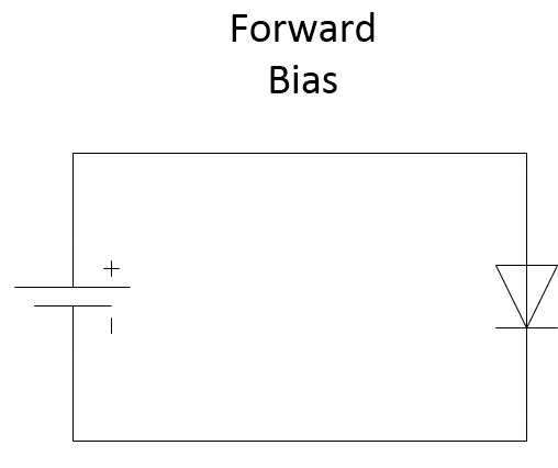
There are bias (applying any source) condition for semiconductor diode. Forward bias and Reverse bias. Diode works only in forward bias. In reverse bias, it blocks the flow of current in circuit or in other words. It becomes open circuit. which is its main property to allow current in only in one direction.


how to forward bias the diode?

We could do it by connecting positive terminal of voltage source from the anode and negative terminal with the cathode. And for reverse bias its vice versa.

How it allows current to flow in forward bias?


It allows current to flow in forward bias, because we connect positive terminal of voltage source with anode and it attracts electron from the N type. So electrons start to flow towards the anode terminal. And there is junction wall between diode, so to overcome there needs voltage of 0.3 or 0.7 . so could say that it is diode starting voltage.


How it blocks current in reverse bias? 


It blocks current in reverse bias, because the positive terminal of voltage source is connected with the cathode so it attracts electron towards cathode terminal so because of it, negative electrons from P type and positive holes from N type goes into junction and increases it. so junction widens and blocks the transfer.


Wednesday, 6 December 2017

Capacitor, definition, formula, explanation, Capacitance

Definition:-

"Capacitor is an electrical device which is used to store energy or charges between its plates."

Explanation:-

Capacitor is use to store charge so that we could use it later by discharging it. It stores electrical charge between its parallel plates which are known as conducting plates of capacitor. There is no connection between these conducting parallel plates. They are separated by air or some dielectric. We use dielectric in capacitor to increase its efficiency. By using dielectric we could store more charge between its plates.
Capacitor doesn't allow dc current to flow through it because DC current flows only in one direction. so, it after charging from dc current it allows to flow through it as there is nothing in the circuit.
While it allows AC current to flow through it because ac current changes its direction after half interval, so capacitor charges at first half and discharges at 2nd half.

Capacitance:-

Capacitance is the ability of a capacitor to store charge. Capacitance tells us that how much charge we can store between the plates of capacitor. Capacitance is the unit of capacitor in one way. While capacitance has unit Farad. Farad is define as,
"When there will be 1 volts across capacitor then it will charge one coulomb, its mean capacitor have one farad capacitance."

Formula:-

By seeing definition of farad we could write formula for the capacitance of capacitor,
Q = CV
C = Q/V

Friday, 1 December 2017

Transformer, Definition, Explanation, working, construction, types

Definition:-

"Transformer is an electrical device that converts low voltage into high voltage or high voltage into low voltage."


Explanation:-

Transform the current or voltage, it is used to get high voltage when input is of low voltage and to get low voltage from high voltage.

Transform works on the principal of Mutual Induction, according to which "When alternating current flows through one winding of coil, due changing nature of ac current, there produce an emf across winding and magnetic flux around winding. When another winding of coil comes near the first winding, there is effect of magnetic flux of first winding on second winding and due to AC current as it changes continuously produces changing magnetic flux of first winding and due to this change there causes the EMF in second winding and hence current starts to flow through second winding, so this process is known as mutual Inductance". Transformer works on this principle. As there is no connection between two coils(we just bring the second nearer to the first), the current transfer will be very small as compared to first. So we use Core to link these two winding, because of this current loss is so small.

Construction:-

 It consists of following,
1.Primary coil
2.Secondary coil
3.Core
4.AC current source

Working:-

Whenever we supplies ac current to primary coil then due to changing nature of ac current there produces change in magnetic flux around this winding. And due to this changing current starts to flow through core and reached to the secondary winding and through this secondary winding goes to external circuit, When we need to change low voltage to high voltage then we have to increase the winding of secondary coil. This type of transformer is known as Step up Transformer. If we want to change the high voltage into low voltage, than we have to decrease the winding of secondary coil. This type of transformer is known as Step down Transformer.